
Sponsor:
Advanced Scientific Computing Research (ASCR) under the U.S. Department of Energy Office of Science (Office of Science)
Project Team Members:
Northwestern University
The HDF Group
- Quincey Koziol
- Gerd Herber
Argonne National Laboratory
North Carolina State University
- Nagiza Samatova
- Sriram Lakshminarasimhan


Damsel Usecase - FLASH
Background
The FLASH code is a modular, parallel multi-physics simulation code capable of handling general compressible flow problems found in many astrophysical environments. It is a Parallel adaptive-mesh refinement (AMR) code with a block-oriented structure - a block is the unit of computation. FLASH code consists of multiple units, which perform specific functionality, e.g. Driver Unit, Grid Unit, IO unit, etc. We will focus on the Grid Unit, implemented via PARAMESH for keeping whole spatial domain, block structures, initialize data, physisolution.pncal variables, etc node It is worth noting two things about PARAMESH and FLASH. First, PARAMESH lost funding so the original developers no longer support it. FLASH effectively took over maintainership. Second, the group is migrating to the Chombo package but this migration will take some time. Chombo's behavior differs significantly from PARAMESH; we will not deal with those differences in this discussion

Here's a high-level block diagramblock_indexing.gif of the various FLASH pieces to show where PARAMESH, the Grid component, fits into everything.
In-Memory Structure
The interesting aspect of the FLASH use case is the way the problem
domain is partitioned into an AMR grid. FLASH uses PARAMESH to build
an oct/quad tree of the blocks in the AMR grid.
Each grid block is a logically Cartesian mesh.
Each block represents a tree node. Blocks are of type LEAF,
PARENT, or ROOT and are numbered using Morton ordering.
The grid is composed of blocks.
Blocks consist of cells: guard cells
and interior cells.
All blocks have the same size
(number of cells).
Cells contain variable values for a
given spatial location.
Physical resolution of blocks
increases by factor of 2 per
refinement level.
Information stored by FLASH

The tree data structure provided by PARAMESH describes grid
block and relationships between those blocks.
Blocks are numbered using a Morton space filling curve.
Each block corresponds to a node in an oct/quad tree.
For each block, PARAMESH stores
refinement level, parent and children in refinement tree, and spatial neighbors that share a face.
Some example figures demonstrating tree structure and grid information:
 refinement level
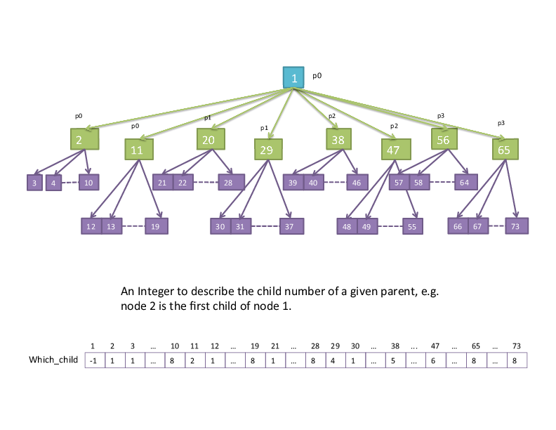 "which child" (parent-child relationships)
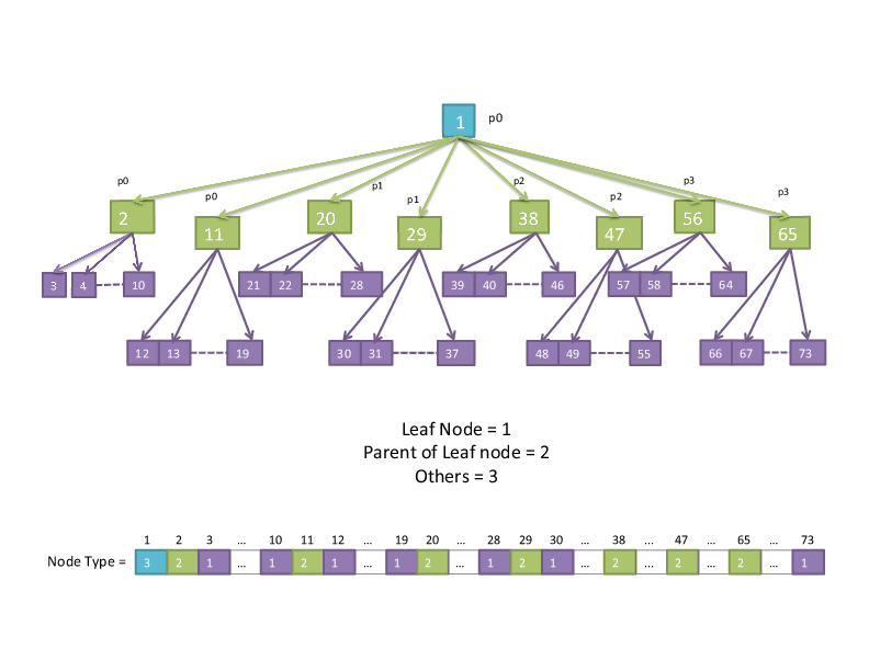 node type (leaf, parent, other)
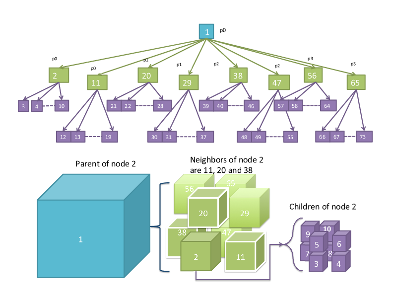 parent, child, and neighbor:

Block location is described by the
midpoint of the block along x, y,
and z dimensions (face-centered, though there are parts of flash that use edge-centered data).
The coordinate interval spanned
by the grid block along each axis
(not the physical length) is stored,
i.e., size of the block.
The lower and upper coordinates
of the block boundaries are stored,
i.e., a bounding box
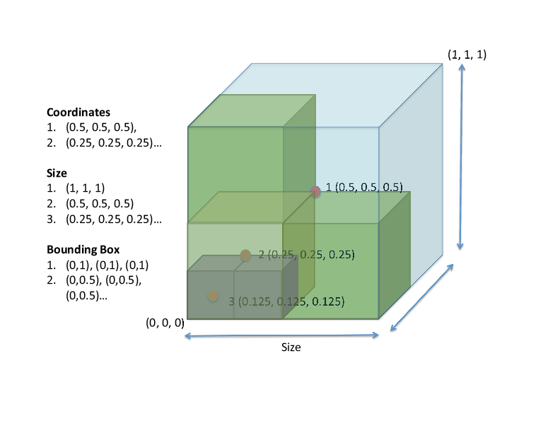
This figure shows how the coordinate, size, and bounding box information fit together.
The solution data means physical
quantities (also known as mesh
variables) such as density, pressure
and temperature.
Physical location of a mesh
variable within grid cell is
described by x, y, and z
coordinates on a block.
This data is stored in a structure containing a
dimension for mesh variables, cells
in each coordinate direction, and
blocks (inside FLASH this variable is called 'unk').
Memory Layout
The cell-centered data is stored in a 5-D array of double precision typed data, named unk. It is allocated once in the PARAMESH package at the start of the FLASH run The array contains a dimension for mesh variables, cells in each coordinate direction, and blocks. First dimension: number of mesh variables (NUNK VARS) Second, third and fourth: cells in each coordinate direction Fifth: Number of maximum blocks per process (MAXBLOCKS) The array is presented in Fortran column major ordering, i.e. the dimension NUNK VARS varies most rapidly.
File Layout
HDF5 and PnetCDF are used for file I/O Only actual blocks (internal cell data) are stored in file Each of the mesh variables is stored into a four-dimensional variable in the file. For each mesh variable, a single variable is copied to a temporary contiguous buffer and then written to the file. There is a contiguous data layout in memory and file.
Summary
Tree information: FLASH uses tree data structure for storing grid blocks and relationships among blocks, including lrefine, which child, nodetype and gid. Per-block meta data: FLASH stores the size and coordinates of each block in three different arrays: coord, bsize and bnd box. Solution Data: Physical variables i.e. located on actual grid are stored in a multi-dimensional (5D) array e.g. UNK.
The tree structure can be reconstructed by maintaining only the child, parent and neighbors information. The meta-data per block can be described by the bounding box information.
FLASH and the Damsel Data Model
Represent AMR Grid, components and relationships
Entities

There are three options for representing cells, i.e. Vertex entities and Quad/Hex entities.
- Option I - each block in the AMR Grid is represented by a vertex in the data model
Since all blocks have the same number of cells, and block variables Lrefine, Which_child, etc. are all fixed-size, and cell variables are stored in 5D arrays, it makes the most sense to allocate blocks as vertices, with fixed-size tags for block and cell variables.
- Option II – Each cell in the AMR Grid as a vertex entity, each block as an entity set
A vertex entity is defined by its coordinates on the grid. There are 408 cells in total each with a different center coordinate in the example, and there will be 408 vertices to represent the AMR grid cells.
- Option III – Each cell as a quad/hex, with vertices forming the connectivity of the cells, each block as an entity set
A cell in FLASH can be represented as a quad or hex entity, but in this case, we need to define all the grid points as vertices and describe the connectivity for each quad/hex entity. Similarly there will be 408 quad entities but with 408*4 vertices?
Comparison of these approaches: Options I and II are mostly equivalent storage-wise, with II using different entity types (vertices and sets) for cells/blocks, and I using entities for blocks and direct storage associated with those entities for cells.
Option I results in storage that looks most similar to what's stored in FLASH, at least in the Paramesh version of it. If in the Chombo-based FLASH all blocks still have the same number of cells, then I looks similar to that too.
If in the Chombo-based FLASH they go to a variable number of cells per block, then option II is probably the best mapping.
Blocks As Vertices
Following option I above, we will represent blocks as vertices in the mesh, with block data set as tags on those vertices. We need to define tags for the following block variables:
- Lrefine
- Which_child
- Coord
- Size
- Boundingbox
- Neighbors
Cells, Cell Variables
Cells will be represented simply by their variables, set as tags on the vertices representing blocks.
Coding Example
Putting it all together, we now describe how the example mesh is written to a MOAB-based implementation.
Global Mesh Definitions
Our example has 17 2D blocks, with each block having 4x6 cells.
const int DIMS = 2;
const int NUMI = 6;
const int NUMJ = 4;
const int NUMK = 1;
const int nblocks = 17;
Blocks
In the example above, there are 17 blocks. To create these we use:
- double coords[3*17] = {... coordinates of blocks, from FLASH coords array ...}
- use moab::Interface::create_vertices (double coordinates[], int nverts, moab::Range new_handles):
moab::Range block_handles;
moab::ErrorCode rval = moab->create_vertices (block_coords, 17, block_handles)
Block data
Use tags to store block data, as follows. The notation used is tag (tag_size per entity * tag data type).
- Lrefine[nb]: tag (1*int)
- which_child[nb]: tag (1*int)
- block_size[3*nb]: tag (3*double)
- Boundingbox[6*nb]: tag (6*double)
- Neighbors[3*nb]: tag (3*entityhandle): for this tag, store the entity handle representing the block neighbor in each direction
  rval = mbImpl->tag_create("lrefine", sizeof(int),
                            moab::MB_TAG_DENSE, MB_TYPE_INTEGER, lrefineTH);
  rval = mbImpl->tag_set_data(lrefineTH, block_handles, lrefine);

  rval = mbImpl->tag_create("whichchild", sizeof(int),
                            moab::MB_TAG_DENSE, MB_TYPE_INTEGER, whichchildTH);
  rval = mbImpl->tag_set_data(whichchildTH, block_handles, which_child);

  rval = mbImpl->tag_create("blocksize", DIM*sizeof(double),
                            moab::MB_TAG_DENSE, MB_TYPE_DOUBLE, blocksizeTH);
  rval = mbImpl->tag_set_data(blocksizeTH, block_handles, block_size);

  rval = mbImpl->tag_create("boundingbox", 2*DIM*sizeof(double),
                            moab::MB_TAG_DENSE, MB_TYPE_DOUBLE, boundingboxTH);
  rval = mbImpl->tag_set_data(boundingboxTH, block_handles, bounding_box);

  rval = mbImpl->tag_create("neighbors", DIM*sizeof(EntityHandle),
                            moab::MB_TAG_DENSE, MB_TYPE_HANDLE, neighborsTH);
  rval = mbImpl->tag_set_data(neighborsTH, block_handles, neighbors);
Cell data
There isn't really any cell data, besides solution data.
Solution Data
Similar to block data, store cell data as one long tag, representing the 4D array per block discussed earlier:
- unk[5,NUMI, NUMJ, NUMK, nb]: tag (5*NUMI*NUMJ*NUMK * double)
  rval = mbImpl->tag_create("unk", 5*NUMI*NUMJ*NUMK*sizeof(double),
                            moab::MB_TAG_DENSE, MB_TYPE_DOUBLE, unkTH);
|
|
EECS Home |
McCormick Home |
Northwestern Home |
Calendar: Plan-It Purple © 2011 Robert R. McCormick School of Engineering and Applied Science, Northwestern University "Tech": 2145 Sheridan Rd, Tech L359, Evanston IL 60208-3118 | Phone: (847) 491-5410 | Fax: (847) 491-4455 "Ford": 2133 Sheridan Rd, Ford Building, Rm 3-320, Evanston, IL 60208 | Fax: (847) 491-5258 Email Director Last Updated: $LastChangedDate: 2014-09-17 14:51:09 -0500 (Wed, 17 Sep 2014) $ |